skip to main |
skip to sidebar
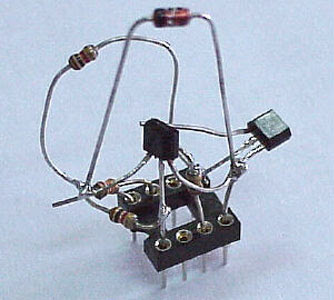
When you need connect your Microcontroller Project to COM port in PC you need RS 232 converter. There are many chip to solve the problem like MAX232, DS275 etc. But if you need simple and chep for RS 232 converter, i though this circuit will be usefull for you. The design made by Wichit Sirichote.

"A circuit diagram shown above was used two small signal transistor, NPN and PNP transistors. Dash line separate transmitter and receiver circuit. For those who need only transmitter circuit can use above circuit (and GND (5) signal ). Technically the RS232C is -3V to -12V for logic '1' and +3V to +12V for logic '0'. The transmitter circuit uses PNP transistor, BC557. While in mark state the TxD signal is logic '1', Q1 turns off. TxD (pin3) then provides -9V (depends on what converter chip being used for COM1, say) to RxD (pin2). For space state, TxD control signal then becomes logic '0', which turns on Q1, the approx. +5V is then fed to RxD (pin2). With this method, while sending data has being made, TxD (pin3) must stable at -9V, say"
There also some modification from above circuit. For more detail you can download here.
[link]
 Evil Mad Scientists have create cool and simple Darkness Sensing LED ever. It's only need few component: a CR2032 lithium coin cell (3 V). LED, an LTR-4206E phototransistor, a 2N3904 transistor, and a 1 k resistor. You can choose it for your first project during learning electronic.
"When light falls on the phototransistor, it begins to conduct up to about 1.5 mA, which pulls down the voltage at the lower side of the resistor by 1.5 V, turning off the transistor, which turns off the LED. When it’s dark, the transistor is able to conduct about 15 mA through the LED. So, the circuit uses only about 1/10 as much current while the LED is off. One thing to note about this circuit: We’re using a red LED. That’s because the voltage drop across the transistor allows less than the full 3 V across the LED. The full three volts is really only marginal for driving blue LEDs anyway, so two-point-something really doesn’t cut it."
[link]
 When you need connect your Microcontroller Project to COM port in PC you need RS 232 converter. There are many chip to solve the problem like MAX232, DS275 etc. But if you need simple and chep for RS 232 converter, i though this circuit will be usefull for you. The design made by Wichit Sirichote.
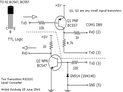
"A circuit diagram shown above was used two small signal transistor, NPN and PNP transistors. Dash line separate transmitter and receiver circuit. For those who need only transmitter circuit can use above circuit (and GND (5) signal ). Technically the RS232C is -3V to -12V for logic '1' and +3V to +12V for logic '0'. The transmitter circuit uses PNP transistor, BC557. While in mark state the TxD signal is logic '1', Q1 turns off. TxD (pin3) then provides -9V (depends on what converter chip being used for COM1, say) to RxD (pin2). For space state, TxD control signal then becomes logic '0', which turns on Q1, the approx. +5V is then fed to RxD (pin2). With this method, while sending data has being made, TxD (pin3) must stable at -9V, say"
There also some modification from above circuit. For more detail you can download here.[link]

"The status and temperature date saved to PC via serial communication. Here 8 temperature sensors are connected(4 shown in diagram for simplicity). values of all the sensors are sent serially by AT89C51 to pc. Software "DAQ System " takes these values and show them on its front panel, and also logs them to the data base "daq.mdb" .we can set some parameters like set point , low limit ,and high limit . when temperature of some sensor increases beyond set point ,the heater connected to controller (specific for that sensor) will be turned OFF( ON in opposite case ).High limit and low limits are for alarm. when temperature goes above high limit or below low limit the alarm will be turned on."
For complete reference, source code, Schematic, you can download here.
[Link]
Do you need an avr counter that can measure for 40Mhz and low cost for this project? Well take a look at microcontroller project : avr counter created by Murray GreenMan. This microcontroller project also give you some interesting feature like : 8 digit LCD display and there is an optioanal PC telemetry so you can watch the output on a PC."The counter contains only three inexpensive ICs (well, add a regulator and three transistors), and operates from 6 - 15V DC at about 25mA. The most expensive single item is the LCD display, which is an industry standard 16 x 2 dot matrix module, which can often be found used or at bargain prices. This isn't a kitset, but the parts are easily obtained, and the circuit can be built using any prototyping technique, or you could design your own PCB. The prototype was built on a small commercial strip board."
[Link]